DC Power Unit Troubleshooting Guide
Warning
When working on a Hydraulic System Always Insure Hydraulic Lines have been depressurized. Hydraulic Injection can cause loss of fingers & even loss of life in severe cases. Hydraulic Injection can seem like a bee sting. If you are ever bitten by Hydraulic Injection go directly to the Emergency Room for Treatment. For more information on Hydraulic Injection contact: Fluid Power Training Institute
The purpose of this guide is to help you trouble shoot KTI DC Hydraulic Power Units, by explaining how the electric & hydraulic circuits work together to perform each function. Also included are some tricks & tips we have found talking to you the customer.
This guide will help you fix the majority of problems you face in the field. If you run into an issue not explained please let us know, our service staff will be more than willing to help solve your issue
Introduction
When troubleshooting Hydraulic Power Units you first want to understand how the hydraulic circuit works with the electrical circuit, Also the sequence of operation for each hydraulic circuit. If you can understand these two things you can fix most hydraulic systems.
Most problems with mobile Hydraulic Power Units are electrical, the most common being poor ground condition which will simulate low battery. Always insure your battery is getting charged. If you are using your hydraulic system frequently you may need to place the battery on charge more frequently.
Never adjust relief valves unless consulting factory. Relief valves are factory preset to the manufacturer’s specification. Adjusting the relief valve will not help the power unit build pressure. The last thing you want to do is adjust the relief valve. Tampering with relief valve could cause injury, catastrophic failure resulting in death.
Having a designated auxiliary battery for your hydraulic system is recommended. Always place a fuse or circuit breaker in charge wire to auxiliary battery. If your battery gets low the Fuse or circuit breaker will blow, if this happens reference battery section in guide.
After you have ruled out the electrical circuit use the Quick Reference Chart to solve your issue. Having a 5000 psi Pressure Gage, Flow Meter & Extra Fitting to Tee in the Pressure Gages will make your job a lot easier.
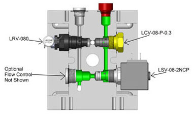
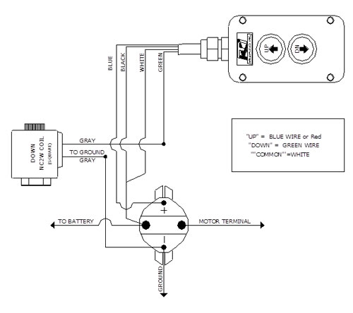
Power Up Gravity Down (Circuit 103)
Extending Cylinder
Pressing UP Button on Yellow Hand Control (not shown) Provides Battery Power to Start Solenoid & DC Motor
- When Start Solenoid (not shown) is activated power is provided to DC Motor (1245-15) which turns gear pump (PL-2.10) to build pressure.
- Fluid travels through the Check Valve (LCV-08-P-0.3) & out the “P” Port to extend the cylinder.
- When cylinder reaches the end of its stroke or maximum load fluid will bypass to tank. Primary Relief Valve set @ 3200 PSI. Relief Valve is Factory Preset, Tampering With Safety Wire Voids Warranty and could result in Serious Injury or Even Death.
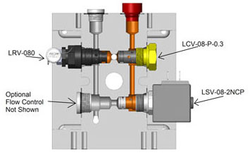
Retracting Cylinder
Pressing Down Button on Yellow Hand Control (not shown) Provides Power to Coil on Solenoid Valve (LSV-08-2NCP).
- Activating Solenoid Opens Normally Closed 2-way Valve Allowing Fluid to return to tank.
- (Optional) When Fluid is returning to tank Flow Control may be placed in manifold controlling the speed of the cylinder retracting.
Single Acting Wiring Diagram
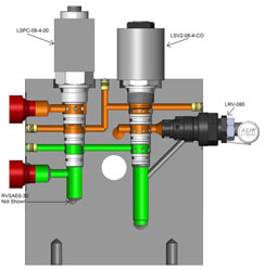
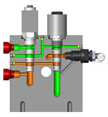
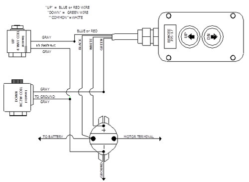
Power Up Power Down (Circuit 111)
Extending Cylinder
Pressing UP Button on Yellow Hand Control (not shown) Provides Battery Power to Start Solenoid, DC Motor & Cylindrical Coil at the Same Time.
- When Start Solenoid (not shown) is activated power is provided to DC Motor (1245-15) which turns gear pump (PL-2.10) to build pressure.
- When Cylindrical Coil (On LSV2-08-4CO) is activated, the Directional Control Valve (LSV2-08-4CO) shifts allowing fluid to travel through the Normally Closed 2-Way section of the Load Holding Valve (LSPC-08-4-00) & out Port A of Manifold which will extend cylinder.
- When the gear pump (PL-2.10) is building pressure to extend the cylinder the Pilot Operated section of Lowering Valve (LSPC-08-4-00) is piloted open to allow fluid from rod end of cylinder to travel back to tank. Pilot Ratio for lowering Valve is 2.5/1
- When cylinder reaches the end of its stroke or maximum load fluid will bypass to tank. Primary Relief Valve set @ 3200 PSI. Relief Valve is Factory Preset, Tampering With Safety Wire Voids Warranty and could result in Serious Injury or Even Death.
Retracting Cylinder
Pressing Down Button on Yellow Hand Control (not shown) Provides Power to Start Solenoid, DC Motor & Square Coil (on LSPC-08-4-00).
- When Start Solenoid (not shown) is activated power is provided to DC Motor (1245-15) which turns gear pump (PL-2.10) to build pressure.
- Pressure flows through Directional Control Valve (On LSV2-08-4CO) then through the Lower Section of Load Holding Valve (LSPC-08-4-00) out Port B of Manifold Retracting cylinder.
- When the Square Coil (on LSPC-08-4-00 is Energized Opening the Normally Closed 2-Way Section of the Lowering Valve (LSPC-08-4-00) allowing fluid to return through Directional Control Valve (LSV2-08-4CO) & back to tank.
- When cylinder reaches the end of its stroke fluid bypasses to tank via 2nd relief valve (RVSAE6-30) set @ 1500 psi. 2nd relief valve is in place to prevent over pressurization of rod end of cylinder & thermal expansion.
Double Acting Wiring Diagram
Low Voltage & Battery Issues
Low Voltage causes high amp draw which equals increased heat & reduced rpm of DC Motor. Many times low voltage will actually be poor ground condition. Low voltage will cause carbon buildup on contacts of start solenoid, coils on directional valve to fail & melt the resin on the field windings of dc motor (you will smell it & see the smoke when this happens).
Low Voltage can be caused by improper sized wire, poor connections, corrosion, auxiliary battery not being charged or possible blown fuse on charge wire.
Trick: By attaching one end of jumper cables to the negative side of the battery & the other to the aluminum manifold, you can improve the ground condition. This is a fast way to check for poor ground
Battery Cable Selection Guide
| Amps | < 5 Ft. | 5-10 Ft. | 10-15 Ft. | 15-20 Ft. | 20-25 Ft. | 25-30 Ft. |
|---|---|---|---|---|---|---|
| 100-150 | 4 Gauge | 2 Gauge | 0 Gauge | 02 Gauge | 02 Gauge | 03 Gauge |
| 150-190 | 4 Gauge | 1 Gauge | 02 Gauge | 03 Gauge | 04 Gauge | 04 Gauge |
| 190-250 | 2 Gauge | 0 Gauge | 02 Gauge | 04 Gauge | 04 Gauge | 04 Gauge |
| 250-300 | 0 Gauge | 02 Gauge | 03 Gauge | 04 Gauge | 04 Gauge | 04 Gauge |
Relief Valve
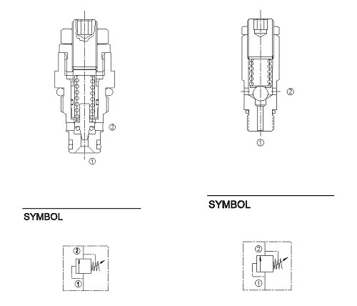
Common Problems with Relief Valves
- Debris stuck on valve seat causing relief valve not to build maximum system pressure
- Adjustment screw being screwed in all the way causing the spring to compress & crack early or not be able to be readjusted to specified pressure setting. (most relief valves will start to crack 100-300 psi before full bypass)
- Torn or extruded O-rings
Check Valve
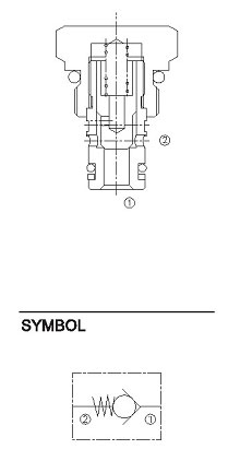
Common Problems with Check Valves
- Debris stuck on valve seat
- Torn or extruded O-rings
- Silting – Debris buildup in valve causing poppet not to move freely
Normally Closed 2-Way

Common Problems with Normally Closed 2-Way
- Debris stuck on valve seat
- Torn O-rings on nose
- Silting – Debris buildup in valve causing poppet not to move freely
- Bent Stem on valve (Stem is the portion of the valve the coil slides over)
Directional Control Valve
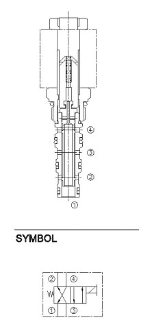
The tolerances between the spool & the cage are tight & overtime these tolerances can increase causing the valve to have excessive leakage. You might notice this if over time, the cycle times have been increasing where eventually you won’t be able to lift a load.
Common Problems with Directional Valve
- Electromagnetic coil not activating
- Over torqued valve (18ft-lbs. Max)
- Torn or extruded O-rings
- Debris stuck in valve
- Rust inside valve preventing spool from shifting
- Bent Stem on valve (Stem is the portion of the valve the coil slides over)
Ways to Check Directional Control Valve
- Valve not shifting
- Ensure valve is not bent (stem is the section of valve the coil slides over)
- Remove valve from manifold
- Use dipstick on breather to push in section 1 on nose of valve. This will manually shift the valve.
- If you can’t shift the valve check for debris & or replace
Trick: By removing the white wire from the start solenoid you can place the coil back on the valve & shift the valve after it has been removed from the manifold. The valve should shift just as fast as you press the button if you see the valve hesitate to shift clean valve & try again. If problem persists replace valve
- Valve stuck in activated position
- After removing valve check spool to see if it is covering the bottom half of the crossed drilled holes in section 2 of valve
- In the valves spring offset position valve should cover the bottom half of the crossed drilled holes on section 2 & 4
Load Holding Valve
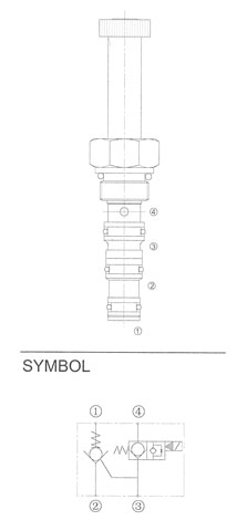
Common Problems with Directional Valve
- Debris in check valves
- Bent Stem on valve (Stem is the portion of the valve the coil slides over)
- Air in system not allowing pilot operated check valve to open
Trouble Shooting Quick Reference Guide
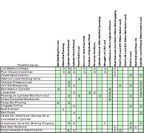
Symptoms and Solutions
- Not Building Pressure
- Gear pump not priming
D/A Remove relief valve operate pump for a few seconds until fluid comes out of port replace relief valve.
S/A Same as double acting but remove check valve - Loose inlet on gear pump
- Bad O-rings on relief valve or directional valve
- Gear pump not priming
- Motor Not Running
- Check Power to Start Solenoid
- Check for Power to DC Motor
- Check for Rust in DC Motor if a. & b. checked out ok
- Cylinder Won’t Extend
- Check Voltage @ Start Solenoid when trying to run Power Unit (Voltage May be below 9.5 volts)
- Check to see if power unit is bypassing over the relief valve
- Improper fluid in reservoir (viscosity to high)
- Check Directional Valve Section D/A
- Check Packing on Cylinder Section
- Cylinder Won’t Retract
- Check to see if coil on load holding valve is activating
- Check Directional Control Valve D/A
- Pilot operated check valve not opening D/A
- Low voltage or poor ground D/A
- Excessive Heat From Unit
- Low Battery
- Poor ground
- Reservoir Overflows
- Low Battery D/A
- Poor Ground D/A
- Air in hydraulic system
- To small of reservoir
- Struggles to Lift Load
- Low battery
- Poor ground
- Gear pump sucking air
- Directional valve half shifting D/A
- Debris in relief valve
- Start Solenoid Just Clicks-Motor Not Engaging
- Carbon buildup on contacts in start solenoid
- Rust inside motor
- Loose wire from start solenoid to DC motor
- Cracked housing on start solenoid
- Won’t Lift Load (DC Motor Not Under Load)
- Low fluid level
- Loose inlet on gear pump (air being introduced into hydraulic System)
- Gear pump not priming
D/A Remove relief valve operate pump for a few seconds until fluid comes out of port replace relief valve.
S/A Same as double acting but remove check valve - Worn out packing on cylinder
- Start Solenoid Stays On
- Low battery or poor ground caused start solenoid to weld on (replace start solenoid & check Battery & ground)
- Cylinder won’t Retract Motor Under Load D/A only
- Low Battery
- Poor Ground
- Coil on load holding valve not energizing
- Directional control valve not returning to spring offset position
- Bad packing in cylinder
Note: D/A notes solutions are for double acting hydraulic circuit