Installation Instructions: 12 VDC Double-Acting
Installation Instructions: For 12 VDC, Hydraulic Power Units, Double-Acting (Power UP / Power DOWN)
Download the or use the tabs below for the Installation Instructions.
- When stowing your three piece remote pendant, it is recommended that you store the remote switch box portion in your vehicle. This will help preserve the new condition of the remote control and prevent theft.
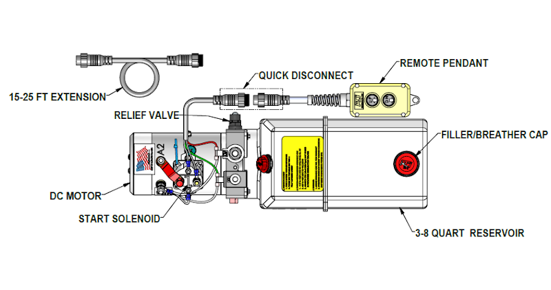
- Remove the two-button pendant from the power unit at the quick disconnect.
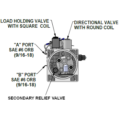
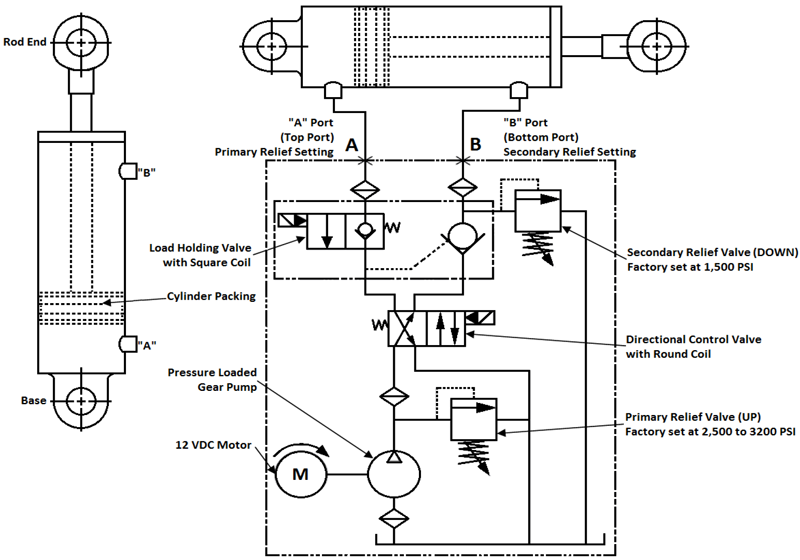
- Install 9/16-18 SAE ORB, SAE #6, hydraulic fittings into ports “A” and “B.” Torque fittings to 18 ft.-lbs.
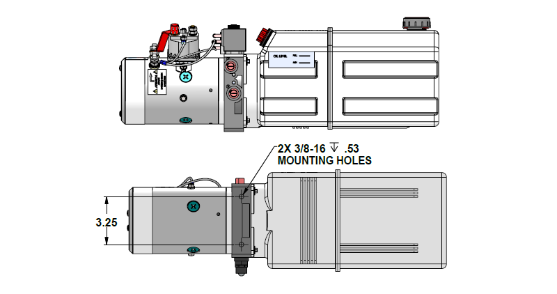
- Mount the Power Unit using two, 3/8-16 x 3/4 mounting bolts (Diagram A-3).
- Connect Hydraulic Lines to ports “A” TOP & “B” BOTTOM (Diagram A-4).a. Connect the “A” port hose to the base of the cylinder.b. Connect the “B” port hose to the rod end of the cylinder.
- Remove the Filler/Breather Cap and fill the reservoir with hydraulic approximately 1 inch from the top (Please see fluid recommendations)
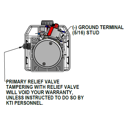
- Connect the battery Ground cable to the Ground terminal of the DC Motor (Diagram A-3).
- Connect the Positive cable from the battery to the start solenoid (diagram A-5). Please see Battery Cable recommendation for proper cable length to use for your hydraulic power unit.
- Use a wrench to hold the bottom nut in place, to torque the upper nut (to 3 ft.-lbs.) to fasten the battery connections.
- Reconnect the two-button remote pendant at the quick disconnect.
- Operate the power unit while keeping an eye on the fluid level in the reservoir.
a. Insure that the fluid level doesn’t go lower than 1⁄2 full during the initial start-up.
b. When the cylinder is fully extended, the reservoir should be about 1⁄2 full.When running your hydraulic power unit for the first time, do not allow the fluid to drop below the half full level, while raising or extending the hydraulic cylinder. This will cause the power unit to induce air into the system. During activation of the down function, the air in the system will cause aeration of the fluid and overflow the reservoir tank.
c. Refer to the Bleed Cycle Procedure Instructions to purge air from the hydraulic system. - If needed refill the reservoir to the “Full line” labeled on the side of the reservoir. Fluid level should be approximately 1 inch from the top of the reservoir.
- Replace the filler/ breather cap.
Do Not Mix Hydraulic Fluids.
KTI recommends using a premium hydraulic oil to ensure optimum performance and system life. Select oil that has anti-wear properties, rust and oxidation inhibitors, foam inhibitors and good stability. Ex- amples of premium grade hydraulic oils: Chevron Rando HDZ, Mobil DTE 10, DTE 20 series, AMSOIL, and Shell Tellus. Automotive Transmission Fluid (DEXRON III) are acceptable under normal conditions. Aviation Oils such as Valvoline ROYCO series or Mobil Aero HF or HFA may be used in prolonged, ex- treme cold environments.
Do Not Use Biodegradable Hydraulic Fluid with Buna seal, Biodegradable Hydraulic Fluid is compatible with Viton seals (optional).
|
Ambient Temperature Range |
ISO Viscosity Grade |
|
– 20 ̊F to + 32 ̊F (- 29 ̊C to + 0 ̊C) |
15 |
|
+ 14 ̊F to + 120 ̊F (- 10 ̊C to + 49 ̊C) |
22, 32, ATF (Dexron III) |
Battery Cables
To minimize voltage drop, increase the gauge size of the battery cables as the length of the positive and ground cables increase. Low voltage will cause the motor to run higher amps causing damage to other electrical components.
|
Cable Length |
Wire Gauge |
Nominal OD (in.) |
|
1 to 2 feet |
4 gauge |
0.43 |
|
3 to 4 feet |
2 gauge |
0.49 |
|
5 to 7 feet |
1 gauge |
0.56 |
|
8 to 9 feet |
1/0 gauge |
0.61 |
|
10 to 12 feet |
2/0 gauge |
0.66 |
|
13 to 15 feet |
3/0 gauge |
0.72 |
|
16 to 19 feet |
4/0 gauge |
0.78 |
Bleed Cycle Instruction Sheet:
1) Remove the breather cap with dip stick, so you may view the hydraulic fluid while operating the Hydraulic Power Unit.
- a) Press the up button on the hand held remote pendant, to run the trailer bed up 1/3 of the way up. While running the bed up view the hydraulic fluid through the breather cap opening, you may see the fluid returning into the tank. If you see any air pockets or aera- tion of the fluid, please stop and allow the fluid to settle and continue to raise 1/3 of the way up.
- b) Once you reach 1/3 of the way up, press the down button to return the trailer bed or deck to it fully seated position (down).
*Please insure that the fluid level does not drop below the half full level of the reservoir while running the power unit.*
2) Press the up button on the hand held remote pendant, to run the trailer bed up 2/3 of the way up.
- a) While running the bed up view the hydraulic fluid through the breather cap opening, you may see the fluid returning into the tank. If you see any air pockets or aeration of the flu- id, please stop and allow the fluid to settle and continue to raise 2/3 of the way up.
- b) Once you reach 2/3 of the way up, press the down button to return the trailer bed or deck to it fully seated position (down).
*Please insure that the fluid level does not drop below the half full level of the reservoir while running the power unit.*
3) Press the up button on the hand held remote pendant, to run the trailer bed up to the end of
the stroke.
- a) While running the bed up view the hydraulic fluid through the breather cap opening, you may see the fluid returning into the tank. If you see any air pockets or aeration of the flu- id, please stop and allow the fluid to settle, and then continue to raise the bed to the end of the stroke.
- b) Once you reach the full up position, press the down button to return the trailer bed or deck to it fully seated position (down).
*Please insure that the fluid level does not drop below the half full level of the reservoir while running the power unit.*
You may have to repeat these 3 steps more than once to completely purge all of the air out of the system.
If you have any questions, please feel free to contact us.
Telephone: 1-949-752-8818
Email: service@ktihydraulicsinc.com


